Starting with an analogy, let’s consider a little girl on a swing as presented in Figure 1 right). Depending on her thumbs direction the mass repartition will vary a little which will induce a tinny change in the oscillating frequency of the swing. Then if you have an accurate frequency readout, you can in principle know if the little girl has her thumbs parallel or anti-parallel just looking at the swing frequency.
In a very simplified picture this is more or less what physicists have realized with the thumbs being two spins and the swing being an electrical LC oscillator.
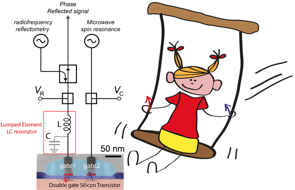
Figure1: Schematics of the setup: a two gates silicon transistor with gate 1 connected to a LC resonator readout by reflectometry and gate 2 connected to a microwave generator to induce spin precession. Girl on a swing: the swing frequency will depend on her thumb's orientation.
Here the researchers hooked-up the LC resonant circuit to a CMOS hole spin qubit device which consists in a nanowire silicon transistor with two gates in series, see Fig1. left In accumulation mode, one gate confines a spin encoding the qubit, the second gate a helper spin for readout. The beauty resides on the fact that there is a tinny capacitive change of the device if the spins in the two dots are parallel or anti-parallel
i.e.:
C_
parallel≠C_
antiparallel.
Finally, the LC oscillator frequencies will be:
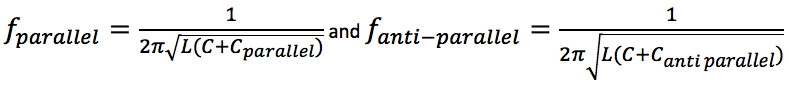
Putting numbers, for a LC resonating at 600MHz, this gives a change leading to 20ppm frequency change. The researchers have then applied a microwave tone to gate 2 to rotate the 2nd spin underneath. The angle of rotation depends on the time duration of this tone (τ
burst). In this condition the two-spin system is oscillating between the parallel and the anti-parallel configuration. This oscillation is visible in Figure 2 which shows the change of frequency ∆ƒ of the LC oscillator as a function of the microwave frequency and the microwave burst time.
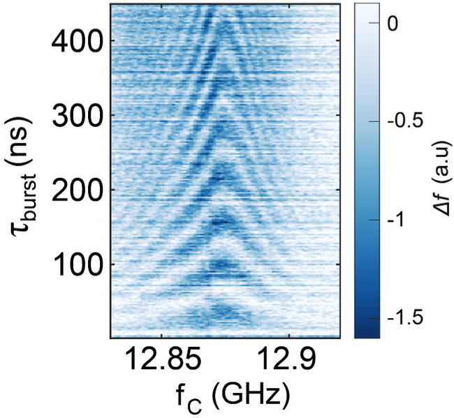
Figure 2: Oscillation between the parallel and antiparallel spin states detected as a frequency change of the LC resonator coupled to the qubit device.
Finally, this demonstrates that dispersive gate reflectometry can be used to readout the spin states of a silicon nanowire transistor. This detection method does not need local reservoirs of charges or embedded charge detectors. This in principle could be used to scale spin qubit architecture where spin readout would be performed by any gate of a 2D quantum dot array by attaching a LC resonator to it.